Sfb290
TP A2 UP III: Scanning tunneling microscopy and UHV-SQUID magnetometry
(K. Lenz,
R. Nünthel, J. Lindner, B. Michaelis, K. Baberschke)
This part describes absolute
measurements of magnetic moments on ultrathin films performed by a
novel in situ (UHV-compatible) high-TC-SQUID magnetometer
and real images of the surface morphology of ultrathin films as they
are recorded by Scanning Tunneling Microscopy (STM).
- Absolute magnetometry on ultrathin 3d metal films by UHV-SQUID
- The T C-jump in Co/Cu(001) films as seen by SQUID and STM
 Fig.
1
Fig.
1A novel UHV SQUID magnetometer was recently built up. A commercial SQUID magnetometer with a high-TC SQUID sensor was installed inside a liquid nitrogen dewar at a flange of an ultrahigh vacuum chamber. By scanning the sample, i.e. an ultrathin film evaporated on a single crystalline substrate like Cu(001), parallel to the SQUID plane the stray field is directly measured and the magnetization of the film is determined. The SQUID is calibrated once with the help of Helmholtz coils and it does not need any reference sample. Therefore, it is an absolute magnetometry. The basic schematic setup and the principle diagram of operation are shown in Fig. 1. Together it is presented the stray field of a 2.9 ML Co/Cu(001) at room temperature. A very high signal to noise ratio of 40:1 is achieved with a single scan. The chamber offers the opportunity to use all conventional techniques for the characterization of thin films (LEED, AES etc.) and has capabilities of cooling with Liquid Helium resulting in an optimum temperature of 40 K at the sample position. In the inset of Fig. 1 we see temperature-dependent measurements for 2 ML Co/Cu(001). Extrapolating to T=0 and dividing by the number of magnetic atoms one obtains the magnetic moment per atom [Ref. 251] . This new SQUID magnetometry was applied to study the thickness dependence of the magnetic moments of ultrathin Co/Cu(001) films and the effects of capping. The results are plotted in Fig. 2. One may see a linear dependence of the magnetic moments with the inverse thickness. At the large thickness limit the samples behave bulk-like while at the limit of 2 ML an enhancement (reduction) of the magnetic moment is encountered for the uncapped (capped) films. Linear regression of the two data sets may provide a bulk-like volume contribution, enhanced surface and reduced interface moments as they are indicated in Fig. 2 [Refs. 238, 254] .
 Fig. 3
For Co/Cu(001) ultrathin films a sudden jump of the Curie temperature occurs as a function of the film thickness d at about 1.8 ML due to the coalescence of the Co islands upon completing the second ML, Fig. 3 [Ref. 211] . Recently we have found an irregular metastable behavior of Co/Cu(001) films with d at and just below 1.8 ML. Namely, by soft heat treatment the T C of films as well as their magnetization increases. The magnetization increase is visualized in Fig. 4 for Co/Cu(001) films with thickness 1.3-1.7 ML. Measurements were performed at 60 K by our novel UHV SQUID. STM experiments for 1.7 ML Co/Cu(001) films show that the meandering islands of a 1.7 ML Co/Cu(001) film in the as deposited state (Fig. 5(a)) merge together after soft heat treatment (Fig. 5(b)) supporting the ideas of [Ref. 211] that the island coalescence is the reason for the TC-jump. In the same Figure characteristic linescans are included to illustrate the profile of the surface of both images.
|
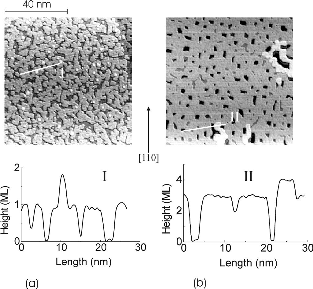
Fig. 5 |
- Influence of surface roughness on the critical thickness for the spin reorientation in Ni/Cu(001)
-
Using STM and MOKE a direct correlation between real space
structure and MAE was studied quantitatively. The influence of surface
roughness on the surface contribution to the magnetic anisotropy energy
was investigated quantitatively. The roughness parameters were taken
from STM images (Fig. 6(a)) and by using a model of P. Bruno the roughness
induced correction on the MAE was calculated (Fig.6(b)). The correction
is small. For example the spin-reorientation thickness for Ni/Cu(001)
shifts by less than one monolayer to a smaller thickness .
Fig. 6:
(a) 24x24 nm 2 STM image of 9 ML Ni/Cu(001) and (b) the
corresponding
configuration of P. Bruno's model
[Ref. 224]
STM can be used to observe mechanisms which improve the growth of ultrathin
film structures. Such a mechanism is provided by using surfactants during
the film deposition. In many cases gases can be used for this purpose. In
case of magnetic thin films the growth with the help of surfactants may –
besides the structural changes – also lead to changes of the magnetic properties.
Figures 7-9 show the result of using oxygen as surfactant during the growth
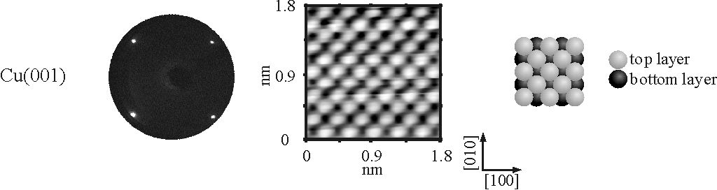
of Ni on Cu(001). In Fig. 7 a STM images of the bare Cu(001) surface together
with its 1x1 LEED pattern is presented. The right picture shows the corresponding
hard sphere model of the fcc (001) surface which can be imaged by STM with
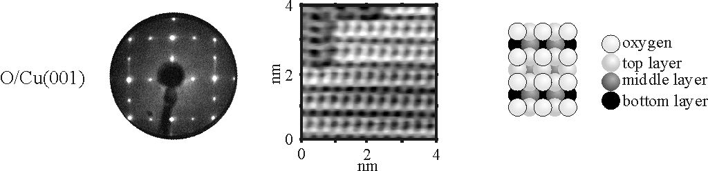
atomic resolution. Fig. 8 shows the Cu(001) surface after dosing 1200L
of oxygen at elevated temperatures. LEED as well as STM reveal the well-known
![]() missing row reconstruction. The missing rows and
the oxygen atoms can be resolved within the STM image from which the hard
sphere model can be derived. The saturation coverage of oxygen is 0.5 ML-equivalents,
so that the amount of oxygen acting as surfactant can be well controlled.
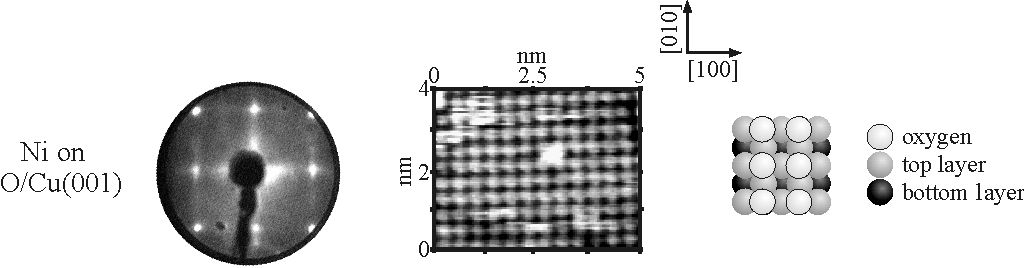
The result after a 5.5 ML thick Ni film has been deposited onto the preoxidized
Cu(001) surface is presented in the Fig. 9. The LEED pattern reveals a
structure resulting from the oxygen atoms that have detached from the Cu
substrate and successively swim on top of the growing Ni film. This is shown
by the STM image where the c(2x2) structure can be observed. The scenario
suggested by the STM and LEED investigations could be confirmed by AUGER
electron spectroscopy, element-specific NEXAFS results and also by theoretical
calculations, for details see Ref.[270].
missing row reconstruction. The missing rows and
the oxygen atoms can be resolved within the STM image from which the hard
sphere model can be derived. The saturation coverage of oxygen is 0.5 ML-equivalents,
so that the amount of oxygen acting as surfactant can be well controlled.
The result after a 5.5 ML thick Ni film has been deposited onto the preoxidized
Cu(001) surface is presented in the Fig. 9. The LEED pattern reveals a
structure resulting from the oxygen atoms that have detached from the Cu
substrate and successively swim on top of the growing Ni film. This is shown
by the STM image where the c(2x2) structure can be observed. The scenario
suggested by the STM and LEED investigations could be confirmed by AUGER
electron spectroscopy, element-specific NEXAFS results and also by theoretical
calculations, for details see Ref.[270].